By FcForged Editorial Team
Precision manufacturing turns an approved wheel design into a physical wheel. In the forged wheel manufacturing process, the starting blank, machined geometry, surface finish, and construction each have a different role. Understanding those roles helps explain what happens between design approval and the completed product.
This guide follows that work through CNC machining, finishing, and construction-specific assembly. It focuses on how the wheel is made, with the approved drawing and specification providing the reference throughout production.
Start Forged Wheel Manufacturing with an Approved Specification
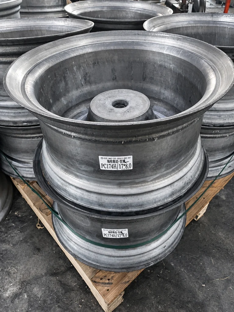
The forged blank provides the starting form; the approved specification defines what it needs to become. A blank is not yet the finished custom wheel. Subsequent machining develops the profiles and features required for the selected design.
FcForged’s standard material offering includes 6061-T6 forged aluminum. The material and blank for a particular project still depend on the agreed construction, dimensions, and design. A material name alone does not describe the complete manufacturing route.
FcForged requires confirmation of the final drawing and specifications before production. That approved version becomes the reference for the work that follows. If you are still choosing the appearance or reviewing a rendering, start with the custom forged wheel design and approval guide.
Turn and Mill the Wheel Geometry
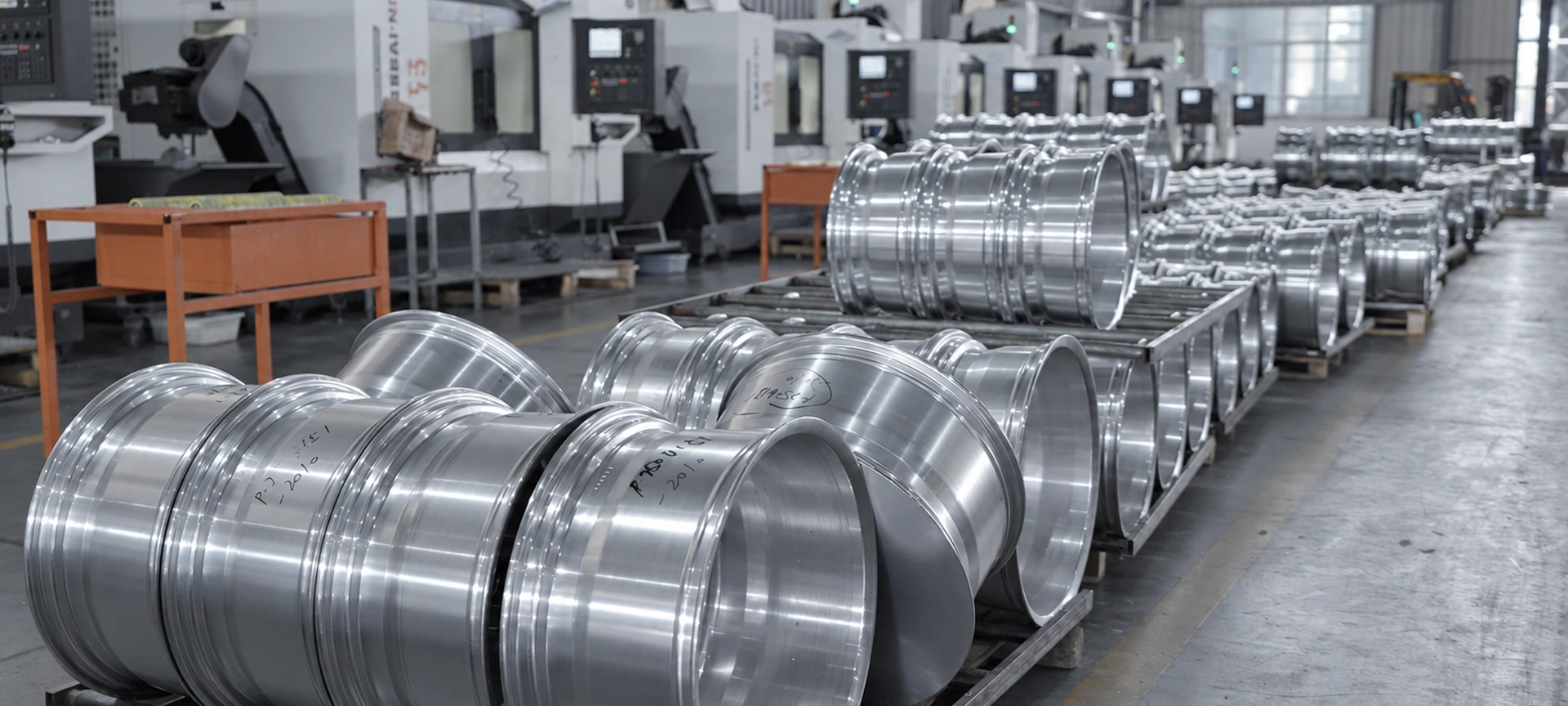
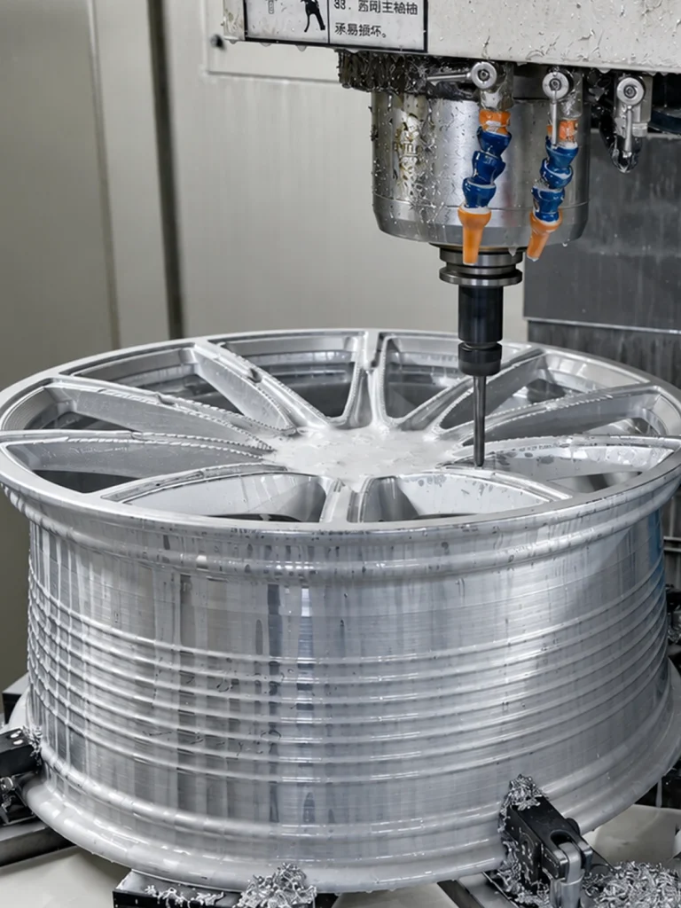
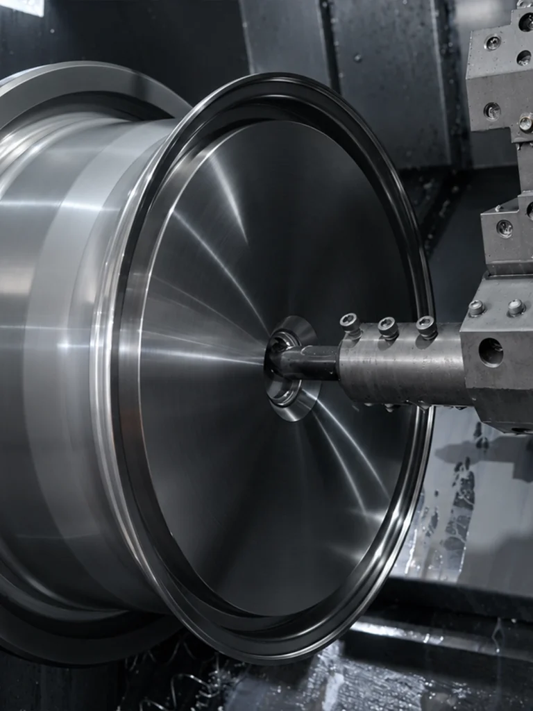
CNC machining removes material to develop the geometry defined by the design. Turning forms circular profiles, while milling creates features such as spoke openings and face details. Hole machining produces the specified openings. These operations contribute different features to the same wheel or component.
| Manufacturing operation | What takes shape |
|---|---|
| Turning | Circular profiles of the wheel or component. |
| Milling | Spoke openings, face contours, and other machined details. |
| Hole machining | Openings required by the approved configuration. |
This is a guide to the roles of the operations, not a fixed machining sequence for every order. FcForged lists CNC machining and drilling among its production stages; the actual route depends on the part and its requirements.
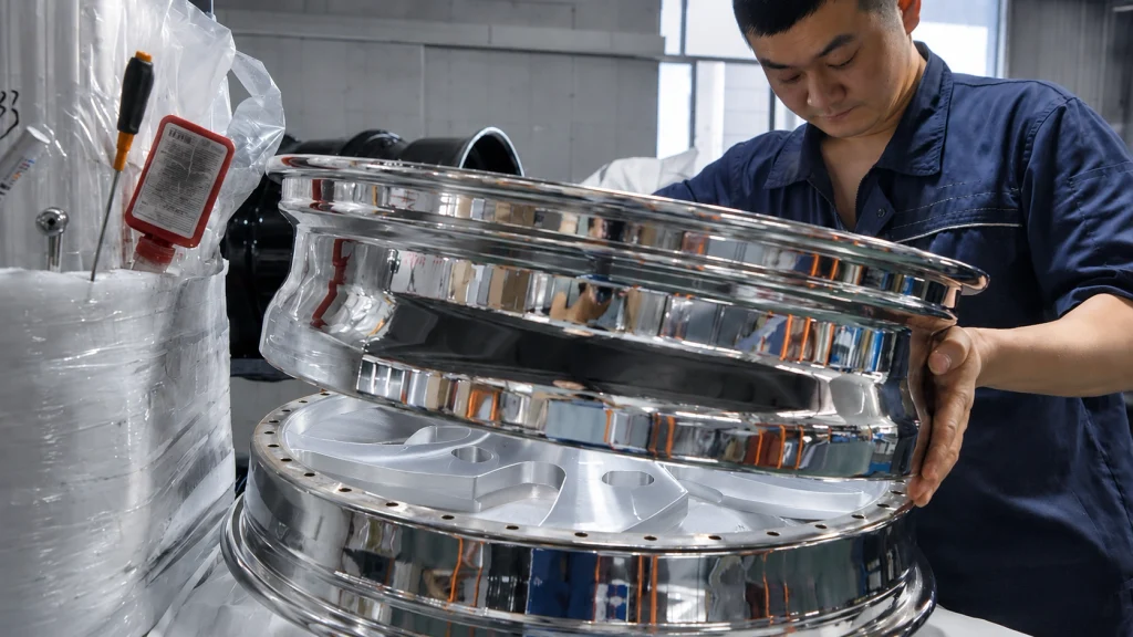
For a monoblock design, machining develops the wheel from a single forging. A multi-piece design has separate components to manufacture and later combine. A production photo is most useful when it identifies the component and the stage shown, so you can distinguish a rough blank, a partly machined part, and a part ready for finishing.
Machine the Mounting Features for the Approved Configuration
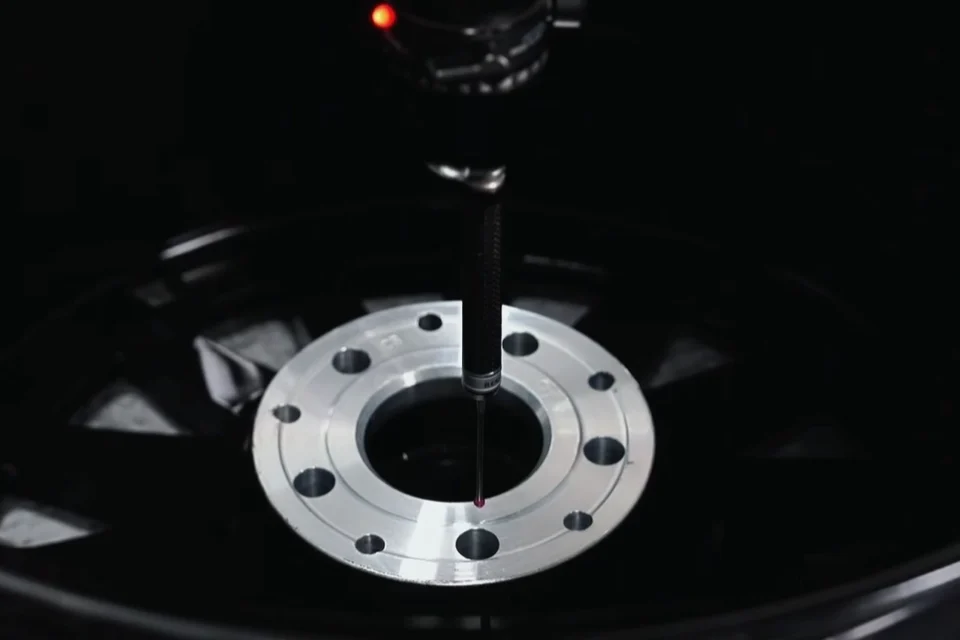
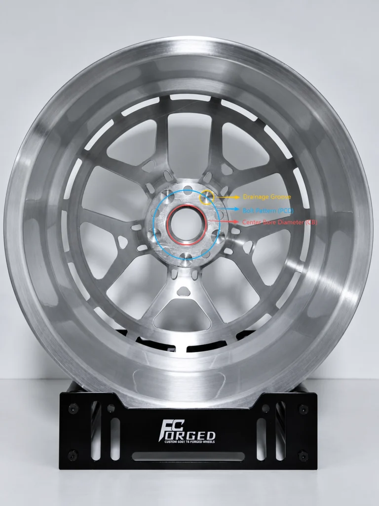
The mounting features are part of the manufactured geometry, even when they are barely visible from the front. The mounting face, center bore, and bolt-hole layout need to follow the approved configuration alongside the spoke design.
This is where customization extends beyond appearance. Two wheels can share a spoke style while requiring different front and rear configurations. The machining work must follow the drawing for the relevant wheel or component, rather than treating a shared design name as a complete specification.
A rear view of a machined wheel helps show this distinction: the visible face is one part of the design, while the mounting area contains features defined by the vehicle application. Their machining requirements belong in the approved technical information before production starts.
Changes to those requirements after machining has begun need review by FcForged. Whether a change is feasible, and how it affects cost or timing, depends on the project and its production stage.
Apply the Approved Surface Finish
Finishing carries the agreed appearance onto the machined part. At this stage, the practical task is to apply the specified surface treatment to the correct areas of the wheel, using the approved appearance reference.
For example, a colored face with a polished lip describes two areas with different finish requirements. The manufacturing plan needs to account for both. This is an illustrative combination; its feasibility and the required work must be confirmed for the particular design.
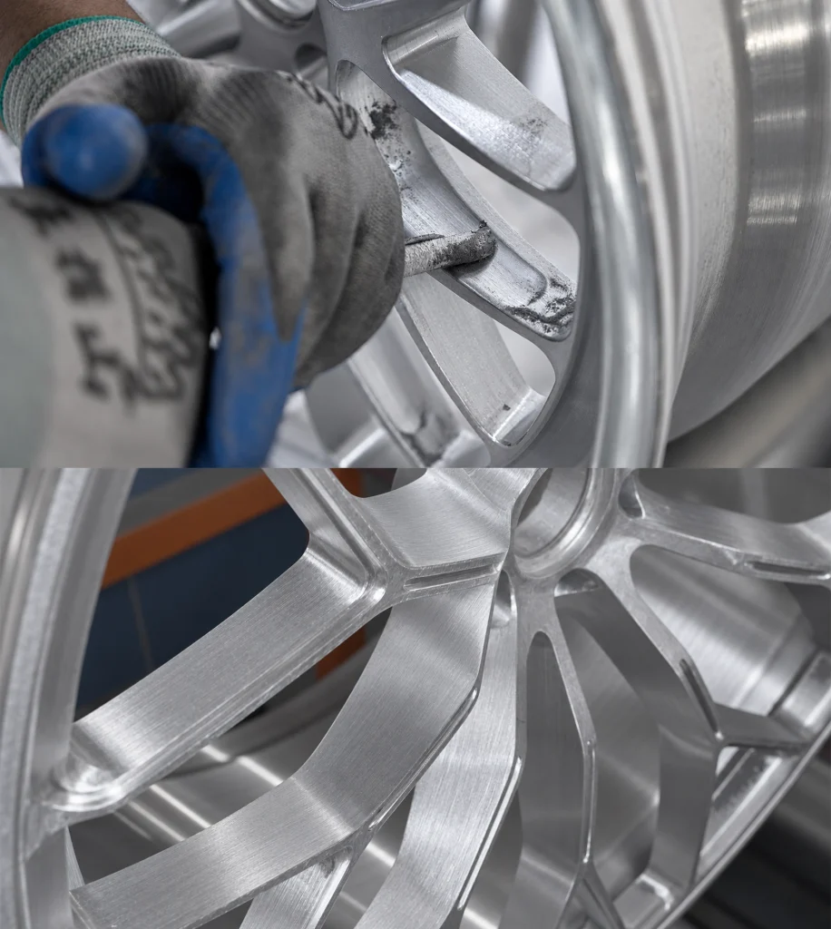
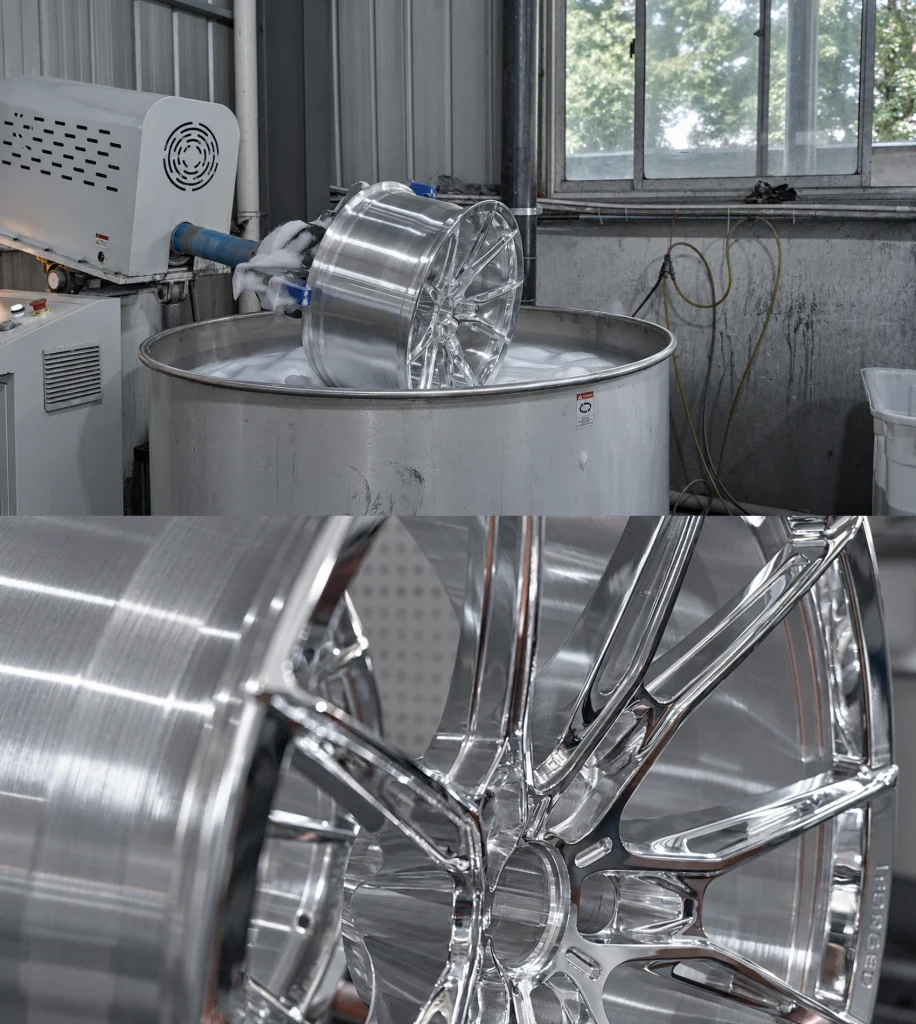
The photos below show surface preparation, a brushed wheel detail, and a polished wheel detail. The preparation and treatment route depends on the specified finish and construction. A reflective surface alone does not identify the coating or treatment used.
For multi-piece wheels, appearance requirements may also differ between the center and the other components. Those differences need to remain identifiable as the parts move toward assembly. The design guide covers choosing the appearance; manufacturing carries that choice onto the physical surfaces.
Complete the Wheel for Its Construction
The final manufacturing work depends on how the wheel is constructed. A monoblock wheel has a one-piece body. A multi-piece wheel brings separately made components together according to the approved construction.
FcForged describes its two-piece options in terms of a face and barrel/lip components, and its three-piece options in terms of a face, inner barrel, and outer lip. The exact component arrangement and assembly requirements must be confirmed for the chosen product. Visible hardware alone does not establish the joining method.
For an order with different front and rear configurations, the components and appearance details need to remain associated with the correct version. A component layout or an assembly-stage photograph can help explain how the separate parts form the completed wheel. It should identify the construction actually shown.
The completed wheel then proceeds to quality inspection against the relevant requirements. Our forged wheel inspection guide explains the dimensions, finish checks, and records to review at that stage.
Planning a project? Use the custom forged wheel quote checklist to organize your starting information, then discuss your manufacturing requirements with FcForged.